The SR-71 was designed
and built by the Lockheed Skunk Works, now the Lockheed Martin Skunk
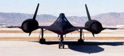
Works. SR-71s are powered by two Pratt and Whitney J-58 axial-flow
turbojets with afterburners, each producing 32,500 pounds of thrust.
Studies have shown that less than 20 percent of the total thrust
used to fly at Mach 3 is produced by the basic engine itself. The
balance of the total thrust is produced by the unique design of
the engine inlet and "moveable spike" system at the front of the
engine nacelles and by the ejector nozzles at the exhaust which
burn air compressed in the engine bypass system. The SR-71 was designed
and built by the Lockheed Skunk Works, now the Lockheed Martin Skunk
Works. SR-71s are powered by two Pratt and Whitney J-58 axial-flow
turbojets with afterburners, each producing 32,500 pounds of thrust.
Studies have shown that less than 20 percent of the total thrust
used to fly at Mach 3 is produced by the basic engine itself. The
balance of the total thrust is produced by the unique design of
the engine inlet and "moveable spike" system at the front of the
engine nacelles and by the ejector nozzles at the exhaust which
burn air compressed in the engine bypass system.
Speed of the aircraft is announced as Mach 3.2 —
more than 2000 miles per hour (3218.68 kilometers per hour). They
have an unrefueled range of more than 2000 miles (3218.68 kilometers)
and fly at altitudes of over 85,000 feet (25908 meters).
As research platforms, the aircraft can cruise at
Mach 3 for more than one hour. For thermal experiments, this can
produce heat soak temperatures of over 600 degrees (F). The aircraft
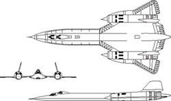
are 107.4 feet (32.73 meters) long, have a wing span of 55.6 feet
(16.94 meters, and are l8.5 feet (5.63 meters) high (ground to the
top of the rudders when parked). Gross takeoff weight is about 140,000
pounds (52253.83 kilograms), including a fuel weight of 80,000 pounds
(29859.33 kilograms).
The airframes are built almost entirely of titanium
and titanium alloys to withstand heat generated by sustained Mach
3 flight. Aerodynamic control surfaces consist of all-moving vertical
tail surfaces above each engine nacelle, ailerons on the outer wings
and elevators on the trailing edges between the engine exhaust nozzles.
Development History
The
SR-71 was designed by a team of Lockheed personnel led by Clarence
"Kelly" Johnson, at that time vice president of the Lockheed's Advanced
Development Company, commonly known as the "Skunk Works."
The basic design of the SR-71 and YF-12 aircraft
originated in secrecy in the late l950s with the aircraft designation
of A-11. Its existence was publicly announced by President Lyndon
Johnson on Feb. 29, 1964, when he announced that an A-11 had flown
at sustained speeds of over 2000 miles per hour during tests at
Edwards Air Force Base, Calif.
 Development
of the SR-71s from the A-11 design, as strategic reconnaissance
aircraft, began in February 1963. First flight of an SR-71 was on
Dec. 22, 1964. The SR-71 last flight took place in October 1999. Development
of the SR-71s from the A-11 design, as strategic reconnaissance
aircraft, began in February 1963. First flight of an SR-71 was on
Dec. 22, 1964. The SR-71 last flight took place in October 1999.
The Manual is the complete SR-71A Flignt Manual
except for approximately 10 pages which are still classified. The
manual contains more than 1000 pages of detailed information about
the SR-71.
Here is a complete table of contents for the SR-71
Flight Manual you will be receiving on your CD.
Section I: Description
and Operation - The Aircraft - Fuel - Engine & Afterburner - Throttles
- Engine Fuel System - Afterburner Fuel System - Fuel Derich System
- EGT Trim System - Inlet Parameters - Exhaust Nozzle & Ejector
- Engine Bleeds - Engine Inlet Guide Vanes (IGV) - Oil Supply System
- Engine Fuel Hydraulic System - Accessory Drive System (ADS) -
External Starter - Chemical Ignition (TEB) System - Air Inlet System
- Spikes - Forward Bypass - Aft Bypass - Inlet Control Parameters
- Automatic Restart - Controls & Indicators - Inlet Control System
- Fuel System - Fuel Tanks - Feeding & Sequencing - Boost Pumps
- Transfer System - Tank Pressurization - Heat Sink System - Air
Refueling System - Controls & Indicators - Electrical System - Batteries
- Emergency AC - External Power - Circuit Speakers - Controls &
Indicators - Hydraulic System - Landing Gear System - Nosewheel
Steering System - Wheel Brake System - Controls and Indicators -
Drag Chute System - Primary Flight Controls - Elevon Control - Rudder
Control - Manual Trim - Surface Limiter - DAFICS - Computer BIT
- DAFICS Preflight BIT - SAS - SAS Logic - Autopilot - Mach Trim
System - Automatic Pitch Warning - APW Controls & Indicators - APW
Operation - Pitot Static Systems - Pressure Transducer Assembly
- Flight & Navigation Instruments - TDI - Airspeed-Mach Meter -
Altimeter - AVSI - AOA - ADI - PVD - Standby Attitude Indicator
- Attitude Indicator - HSI - BDHI - Attitude Indicator-RSO - Accelerometer
- Magnetic Compass - Communications & Avionic Equipment - Interphone
System - Normal Operation - COMNAV-50 UHF Radio - UHF Control Panels
- Remote Frequency Indicator - MODEM Control Panel - Distance Indicator
- UHF Antennas - UHF Operation - AN/ARA-48 Automatic Direction Finder
- AN/ARC-186 (V) VHF Radio - VHF Operation - HF Radio, T - HF Radio,
AN/ARC-190 (V) - Instrument Landing System - ILS Control Panel -
Marker Beacon - IFF Transponder - IFF Control Panel - IFF Normal
Operation - IFF Emergency Operation - G Band Beacon - I Band Beacon
- TACAN System - TACAN Control Panel - TACAN Control Transfer Switch
- TACAN Operation - Windshield - Deicing System - Rain-Removal System
- Canopies (See Page - ) - Rear-View Periscope - Map Projectors
- Pilot's Map Projector - RSO's Map Projector - Lighting Equipment
- Exterior Lighting - Forward Cockpit Lighting - Aft Cockpit Lighting
- Environmental Control Systems - Pressurization Schedules - Controls
- Life Support Systems - Oxygen System - Emergency Oxygen - Full-Pressure
Suit - Torso Harness - Oxygen Mask - Emergency Escape System - Ejection
Seat - Primary Ejection Sequence - Secondary Ejection Sequence -
Egress Coordination System - Emergency Warning Equipment - Master
Warning System - Nacelle Fire Warning - Miscellaneous Equipment
- Trainer Aircraft
Section IA: Description and Operation
- The SR-71 B Aircraft -
Aircraft Gross Weight - Engine and Afterburner - Air Inlet System
- Fuel Supply System - Electrical System - Landing Gear System -
Nosewheel Steering System - Wheel Brake System - Drag Chute System
- Flight Control System - Manual Trim System - DAFICS - Preflight
BIT - SAS/Autopilot Function Selector - APW and High Angle of Attack
Warning Systems - Pitot Static Systems - Flight Instruments - HSI
- Communication & Avionic Equipment - Emergency ICS - Windshield
- Canopies - Lighting Equipment - Environmental Control System -
Life Support Systems - Flight ManualControl Transfer Panels - Inertial
Navigation System - Astroinertial Navigation System - Sensor Equipment
- Mission Recorder - Egress Coordination System - Emergency Warning
Equipment - Miscellaneous Equipment
Section II: Normal Procedures - Introduction
- Crew Coordination - Preparation for Flight - Preflight Check -
Before Entering Cockpit - Front Cockpit Interior Check - Trainer
Aft Cockpit Interior Check - Aft Cockpit Interior Check-SR- A -
Aft Cockpit Check (Solo Flight) - Starting Engines - Clearing Engines
- Aft Towing - Engine Operation - Before Taxiing - Taxiing - Before
Takeoff - Takeoff - After Takeoff - Climb - Acceleration - Cruise
- Prior to Descent - Descent - Air Refueling - Fuel Dumping - Before
Penetration - Penetration - Before Landing - Normal Landing - Wet/Slippery
Runway Landings - Maximum Performance Landing - Go Around - Touch
and Go Landing - After Landing - Engine Shutdown - Survival Quick
Launch - Quick Launch Setup - Quick Launch Start - Quick Launch
Taxi - Quick Launch Takeoff
Section III: Emergency Procedures - Introdcution
- Multiple Emergencies - Assumptions - Symbol Coding - Definitions
of Landing Situations - Use of Checklists - Ground Operation - Emergency
Egress - Engine Fire - Brake or Steering Failure - Anti-skid Out
- Tire Failure - Takeoff Emergencies - Propulsion System - Engine
Failure - Afterburner Failure - Afterburner Nozzle Failure - Fire
- Abort - Barrier Engagement - Tire Failure - Emergency Gear Retraction
- In-Flight Emergencies - Bailout - Forced Landing or Ditching -
Smoke or Fumes - Air Conditioning System Smoke - Electrical Fire
- Emergency Descent - Fuel Dumping (refer to Sec II) Propulsion
System Emergencies - Inlet Unstart - Inlet Malfunction - Manual
Inlet Operation - Compressor Stall - Subsonic Compressor Stalls
- Compressor Stall in Descent - Engine Flameout - Double Engine
Flameout - Airstart - Engine Fire & Shutdown - Single Engine Flight
Characteristics - Single Engine Air Refueling - Afterburner Flameout
- Afterburner Cutoff Failure - Afterburner Nozzle Failure - Fuel
Hydraulic System Malfunction - Abnormal EGT Indications - Accessory
Drive System (ADS) Failure - Oil Pressure Abnormal - Oil Quantity
Low - Fuel Control Failure - Engine Instability During Decel/Descent
- Other Aircraft System Emergencies - Fuel System - Fuel Quantity
Low - Fuel Pressure Low - Tank Pressurization Failure - Fuel System
Management with Engine Shutdown - Sequencing Incorrect - Partial
Loss of Boost Pumps - Complete Loss of Boost Pumps - Electrical
System - Single Generator Failure - Double Generator Failure - Bus
Tie Open - Transformer-Rectifier Failure - Emergency AC Bus Loss
- Hydraulic System - Abnormal Hydraulic Pressure - L & R Systems
- A & B Systems - Flight Control System - Aircraft Control Abnormal
- Trim Failures - Stability Augmentation System - SAS Emergency
Operation - Pitch or Yaw Axis First Failure - Pitch or Yaw Axis
Second Failure - Roll Axis Failure - Analytical Redundancy Failure
- Autopilot Failure - DAFICS Computer Failures - Single Computer
Out - A & B Computers Out - (A & M) or (B & M) Computers Out - A,
B and M Computers Out - APW and High Alpha Warning - Two PTA Channels
Out - Air Data Malfunction - Pitot Static System - Navigation Systems
- ANS Malfunction - INS Malfunction - Environmental Control System
- L or R Air System Out - Cockpit Overtemperature - Cockpit Too
Cold - Cockpit Depressurization - Cockpit Fog - Suit Overtemperature
- E or R Bay Overheat - Life Support Systems - Breathing or Suit
Pressurization Difficulty - Use of Standby Oxygen - Use of Emergency
Oxygen - Contaminated Oxygen - Use of Pressure Suit Air w/o Oxygen
- Loss of Visor Heat - Loss of Suit Vent Air - Drag Chute System
- Landing Emergencies - Single Eng. Penetration & Landing - Simulated
Single Engine Landing - Single Engine Go-Around - Landing Gear System
Emergencies - Gear Unsafe Indication - Gear Emergency Extension
- Partial Gear Landing - Main Gear Flat Tire Landing - Blown Main
Gear Tire After Landing - Nose Gear Flat Tire Landing - Landing
Without Nose Wheel Steering - Flat Strut Landing - Gear Down Air
Refueling - Cockpit Fog - Damaged Refueling Receptacle - Warning
Lights System - Tactical Limits - Emergency Entrance
Section IV: Navigation and Sensor Equipment
- Astroinertial Navigation System - Tape
12 - System Interfaces - Modes of Operation - System Errors - System
Components - Navigation Control/Display Panel - Computer Program
- Mission Tape Program - Mission Modification - Operation - Normal
Procedures - Ground Alignment - Ground Alignment Correct - Ground
Hot Start - Cold Airstart - Hot Airstart - Select Dead Reckon -
Runway Heading Alignment - Fill Present Position - Fill Wind - Fill
Day and Time - Fill Day - Fill Magnetic Variation - Heading Update
- Present Position Update, Using Remote Source Data - Present Position
Update, Using Radar With RCD - Present Position Update, Using Viewsight
- Present Position Update, Using TACAN (Tape Filled Point) - Present
Position Update, Using TACAN (Anytime TACAN FP) - Recall Anytime
TACAN FP - Present Position Update, Using Opportunity Viewsight
FP - Track Leg Update - Direct Steer - Skip to DP - Delete FP, CP
and DP, Clear List - Add Anytime FP - Add or Replace FP, CP, DP
- Normal Display - Display Selected FP, CP, DP - Display Next FP,
CP, DP - Display Day of Year/Star Data - Display Heading - Display
Present Position - Present Display - Display Tape Numbers - Malfunction
Procedures - Inertial Navigation System - INS Operation - Inertial
Control Panel - INS Procedures - Sensor Systems - Power & Sensor
Control Panel - Technical Objective Camera - TECH Normal Procedures
- TECH Malfunction Procedures - CAPRE Side Looking Radar System
- Radar Control Panel - SLR Normal Operation - SLR Malfunction Procedures
- RCD - Optical Bar Camera - OBC Control Panel - OBC Normal Procedures
- OBC Malfunction Procedures - EIP System - Digital Recorder - Continuous
Analog Recorder - EIP Procedures - V/H (FMC) System - V/H Procedures
- Optical Viewsight - Viewsight Control Panel - Viewsight Procedures
- Video Viewsight - Viewsight Controls - Viewsight Displays - Viewsight
Procedures - Exposure Control System - Mission Recorder System -
Center of Gravity Calculator - Defensive (DEF) Systems - Control
Panel - Warning Panel - A System - C System - H System - M System
- Interface/Reliability Checks - Advanced Synthetic Aperture Radar
System (ASARS-1 ) - Radar Control Panel - Inflight Processor and
Display (IPD) - Operating Procedures - Auto - Manual - Malfunction
Procedures - Image Position Update - Altitude Update - Spotlight
Repositioning - Astroinertial Navigation System - Tape - System
Interfaces - Modes of Operation - System Errors - System Components
- Navigation Control/Display Panel - Computer Program - Mission
Tape Program - Mission Modification - Operation - Normal Procedures
- Ground Alignment - Ground Alignment Correct - Ground Hot Start
- Cold Airstart - Hot Airstart - Select Dead Reckon - Runway Heading
Alignment - Fill Present Position - Fill Wind - Fill Day and Time
- Fill Day - Fill Magnetic Variation - Heading Update - Present
Position Update, Using Remote Source Data - Present Position Update,
Using ASARS With IPD - Altitude Update, Using ASARS With IPD - Present
Position Update, Using Viewsight - Present Position Update, Using
TACAN (Tape Filled Point) - Present Position Update, Using TACAN
(Anytime TACAN FP) - Recall Anytime TACAN FP - Present Position
Update, Using Opportunity Viewsight FP - Track Leg Update - Direct
Steer - Skip to DP - Delete FP, CP and DP, Clear List - Add Anytime
FP - Add or Replace Non-ASARS FP, CP, DP - Replace ASARS FP - Add
or Replace ASARS CP - Normal Display - Display Selected FP, CP,
DP - Display Next Non-ASARS FP, CP, DP - Display Day of Year/Star
Data - Display Heading - Display Present Position - Present Display
- Display Tape Numbers - Malfunction Procedures
Section V: Operating Limitations - Introduction
- Minimum crew - Instrument Markings - Fuel - Emergency Fuels
- Engine Operating Limits - In-Flight Shutdown - Exhaust Gas Temperature
(EGT) - Compressor Inlet Temperature (CIT) - Engine Speed (RPM)
- Oil Pressure - Exhaust Nozzle Position (ENP) - Maximum Weight
- Load Factor Limits - Flight Envelope Limits - Maximum Mach - Airspeed
- Angle of Attack - Altitude - High Altitude Turns - Prohibited
Maneuvers - Simulated Single-Engine Flight - Rate of Descent - Center
of Gravity - Pitch Trim Indications While Subsonic - Pitch Trim
Indications While Supersonic - Aircraft Systems Limitations - Surface
Limiter - Stability Augmentation System - Autopilot - Fuel System
- Anticollision Lights - Canopy - Landing Gear - Tires - Brakes
- Drag Chute - Flight Without Pressure Suit
Section VI: Flight Characteristics - Introduction
- Configuration Effects - Angle of Attack - High Angle of Attack
Conditions - Spins - Stability Characteristics - Effects of CG Location
- Normal Operating Characteristics - Takeoff - Climb - Cruise -
Maximum Range (Optimum) Cruise Profile - Normal and Steep Turns
- Maximum Afterburner Ceiling Profile - Maximum Altitude Cruise
Profile - High Altitude Turn Technique - Descent - Air Refueling
- Approach and Landing
Section VII: All Weather Operation Instrument
Flight Procedures - Spatial Disorientation - Pitot-Static Systems
- Before Instrument Takeoff - Instrument Takeoff and Climb - Steep
Turns - Holding - Jet Penetration - Instrument Approaches - Missed
Approach and Go-Around - Single-Engine Operation - Ice and Rain
- Windshield Icing - Visibility In Rain - High Humidity Conditions
- Turbulence and Thunderstorms - Operation in Turbulence - Cold
and Hot Weather Procedures - Cold Day Ground Operation - Hot Day
Ground Operation - Night Flying
Full Appendices and Index
 Bonus
Package : We are also including 44 spectacular photos
of the SR-71 and 6 video clips of the SR-71 in operation on this
CD. The CD is presented as a simple HTML menu layout and works just
like how you navigate web pages (except you do not need to be online
to use this CD.) Bonus
Package : We are also including 44 spectacular photos
of the SR-71 and 6 video clips of the SR-71 in operation on this
CD. The CD is presented as a simple HTML menu layout and works just
like how you navigate web pages (except you do not need to be online
to use this CD.)
Here are the
computer requirements to run and operate this CD. You must have
a PC running Windows or a Macintosh running OS X or higher software
and a web browser. |